 Table of Contents
 Previous Chapter
Table of Contents
Previous Chapter
This section describes the overall architecture of the ACIS Science Instrument Software, and identifies the key interfaces between the hardware and the software, and between the major software components.
The bulk of the ACIS Science Instrument Software resides in the Back End Processor (BEP). This software is responsible for managing commands and telemetry, and for filtering and packing science data. The design of the BEP software employs object-oriented techniques, and uses a commercial real-time multi-tasking executive.
The Front End Processor (FEP) software is responsible for processing raw pixel data as quickly as possible. In general, this software has to deal with only one task at a time. As a result, its design employs a simple interrupt handler and single main thread of control, and takes a structured design approach.
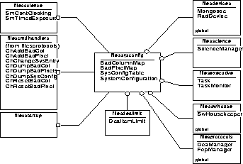
Class categories are a way of grouping related classes. Early in the design, categories were used to logically separate the layers of the design. As the design evolved, the source code directory structure superceded this layering to some extent, although some of the aspects of the layered architecture remain. The following illustrates the current BEP software class category directories (NOTE: ipclgen resides at the same level as the other class cateories):
FIGURE 3. Class Category Directories
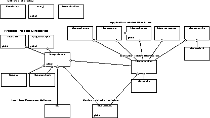
Early in the ACIS design, there were five main categories. As the design evolved, it was discovered that more fine-grained categories were needed to group more tightly related classes. The original category set was as follows:
Finally, all of the Front End Processor software is contained in the fep directory.
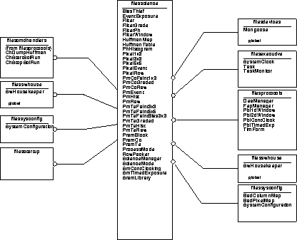
This section illustrates classes contained in each of the main category directories, and the clients and servers of those classes.
The device classes are responsible for directly interacting with the BEP hardware. The detailed design of the BEP device classes is contained in Section 5.0 through Section 12.0 .
FIGURE 4. Device Class List
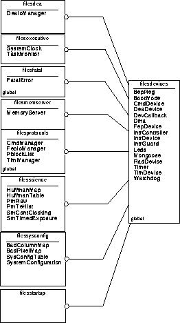
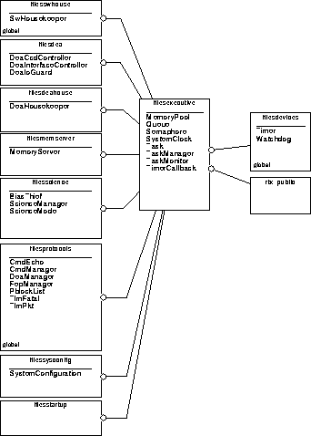
The Executive classes are responsible for providing an interface layer between the main BEP software and the Nucleus RTX executive. The detailed design of the executive classes is described in Section 15.0
FIGURE 5. Executive Class List
The Protocol classes are responsible for managing a variety of interface protocols.
FIGURE 6. Protocol Class List
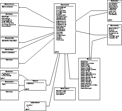
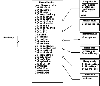
FIGURE 7. Protocols Command Handler Class List
The detailed design is segmented into sections as follows:
Command Management - Section 16.0 covers
CmdPkt
Command Handlers - Section 17.0 covers all of the command handler classes (see Figure 7).
Telemetry Management - Section 18.0 covers
TlmAllocator
TlmCallback
TlmFatal
TlmForm
TlmManager
TlmPkt
TlmPool
TlmQueue
FEP Management - Section 25.0 covers
FepIoManager
DEA Management - Section 26.0 covers
DeaManager
NOTE: Classes provided in filesdea and filesdeacheck have yet to be described. Section is TBD.
Parameter Block Management - Section 20.0 covers
PblockList
NOTE: PblTimedExp, PblContClock, PblDeaHouse, Pbl2dWindow and Pbl1dWindow have yet to be described. Section is TBD.
Fatal Error Reporting - Section 29.0 covers
FatalError
IP&CL Code-Generation - Section 21.0 , Section 22.0 , and Section 23.0 cover
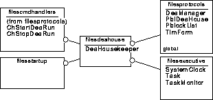
The DEA Housekeeper class is responsible for periodically acquiring and telemetering information from the Detector Electronics Assembly. Its detailed design is provided in Section 31.0
FIGURE 8. DEA Housekeeping Class List
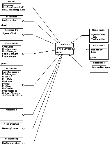
The Software Housekeeper class is responsible for accumulating software housekeeping statistics reported by other software units within the BEP, and periodically telemetering the accumulated data. Its detailed design is described in Section 28.0
FIGURE 9. Software Housekeeping Class List
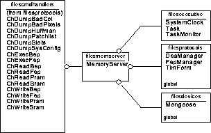
The Memory Server class is responsible for servicing command requests to read (dump) or write portions of the BEP's, FEP's or DEA's memory, and to service command requests to execute code on the BEP or FEP. It uses the FEP Manager and DEA Manager classes to respectively forward requests to the FEP and DEA, when needed. Its detailed design is described in Section 27.0
FIGURE 10. Memory Server Class List
The System Configuration classes are responsible for maintaining the system configuration table, and the Bad Pixel and Column maps.
FIGURE 11. System Configuration Class List
The detailed design of the classes are located as follows:
System Configuration Table Management - Section 30.0 covers
SystemConfiguration
Bad Pixel and Column Map Management - Section 32.0 covers
The Science Management classes are responsible for a variety of activities involved in performing a science run, including run setup and execution and bias-map transmission.
FIGURE 12. Science Class List
The detailed design for the science classes is broken into several sections, as described below:
Science Management - Section 33.0 covers
Science Data Processing - Section 37.0 covers
PmEvent


PmHist


PmRaw


PmTeFaint3x3


PmTeFaintBias3x3


PmTeGraded


PmTeHist


PmTeRaw


SmContClocking
SmTimedExposure
NOTE: Pixel5x5 and PmTeFaint5x5 have yet to be described. Section is TBD.
Bias Map Telemetry Management - Section 38.0 covers
Huffman Data Compression - Section 24.0 covers
SRAM/PRAM Setup - Section 36.0 , Section 34.0 and Section 35.0 cover
The Back End Processor runs a preemptive, multi-tasking executive. During BEP start-up (see Section 14.0 ), all of the system's tasks are started. Once started, these tasks never exit. Tasks of a given priority are allowed to preempt tasks of a lower priority, and tasks of the same priority run until they are either preempted, or until they sleep for some period of time or relinquish control, at which point another task of the same priority is permitted to run. Once all tasks of a given priority are blocked, waiting for an event to occur, tasks of a lower priority are allowed to run.
The architecture of the BEP relies on a set of concurrently running tasks. Each task is represented by an object of a specific sub-class of the Task class. The following lists the BEP's tasks, listed and grouped according to their priority (highest priority, 51, is first, and lowest priority listed, 55, is last. Tasks with the lowest priority number have the highest run-time priority):
--------------------------------------------------------------------------------- Class Name Pri. Object Name Role ---------------------------------------------------------------------------------TaskMonitor51taskMonitorPerform aliveness tests of the other tasks. Allows the watch dog timer to reset the BEP if a task fails to respond to a query within 8 minutes.CmdManager52cmdManager Execute uplinked commandsSystemConfiguration53systemConfiguration Respond to changes in config uration table and monitor the radiation flagSwHousekeeper53swHousekeeper Collect and periodically send software statistics. Update LED bi-levels to reflect instru ment's operating state.DeaHousekeeper53deaHousekeeper Periodically collect and send DEA housekeeping values.MemoryServer54memoryServer Handle read (including dump), write, and execute memory commandsBiasThief55biasThief Trickle the contents of the computed CCD bias maps to telemetry.ScienceManager55scienceManager Perform science run, including hardware setup, parameter dumps, bias computation and data processing ---------------------------------------------------------------------------------
Each BEP task class provides two sets of member functions. One set is visible to clients of the class and may be called directly by any thread of control. In this document, these are known as "binding" functions. The second set of functions are internal to the task class, and must be called only by the task object's thread of control.
This section identifies the some of the objects within ACIS which are globally visible to the rest of the system. Figure 13, "BEP Global System Objects," on page 70 illustrates the key higher level global objects within the ACIS software. In that figure, the solid-lined "clouds" represent objects, and the connecting lines show who is talking to whom. The filled boxes indicate that the object is exclusively used by the party at the other end of the line. The empty boxes indicate that the adjacent object is shared by several other objects.
FIGURE 13. BEP Global System Objects
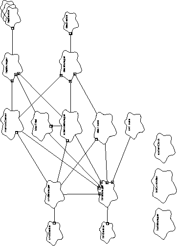
Devices
cmdDevice - This object is responsible for physically reading
command packets from the BEP's command hardware.
tlmDevice - This object is responsible for setting up the teleme
try hardware to transfer the contents of a region of memory to the
RCTU serial telemetry port.
deaDevice - This object is responsible for writing commands to
the DEA command port, and for reading status words from its reply
port.
fepDevice[6] - Each object corresponds to a single FEP. These
objects are responsible for accessing the FEP control hardware and
for accessing memory-mapped hardware and software mailbox
locations within the corresponding FEP.
Protocols
cmdManager - This object is responsible for acquiring commands
from the cmdDevice and executing the commands. It uses the
tlmManager, via a cmdLog object (not shown), to acknowledge
the reception of commands and indicate their disposition.
tlmManager - This object is responsible for queueing telemetry
transfer requests from the many telemetry sources within the sys
tem. The tlmManager uses the tlmDevice to instruct the hard
ware to physically transfer the telemetry items.
deaManager - This object is responsible for formatting and send
ing commands to the Detector Electronics Assembly, and for pro
cessing any acquired status information and data. This object uses
the deaDevice to issue command and retrieve responses from the
physical DEA hardware.
fepManager - This object is responsible for commanding all of
the FEPs and for managing data being produced by the FEPs. This
object uses all of the fepDevice and fepIoManager objects to
send and receive information to and from the individual FEPs.
fepIoManager[6] (not shown) - These 6 objects are responsible
for managing the I/O protocol to and from each of the Front End
Processors. Each manager corresponds to a single FEP.
Applications
memoryServer - This object is responsible for performing mem
ory dumps, run-time memory loads, and commanded function calls.
It uses the fepManager to forward such requests to the FEPs and
the deaManager to perform DEA memory loads and dumps. The
memoryServer uses the tlmManager to transfer memory
dumps and send return values from function calls into telemetry.
scienceManager - This object is responsible for managing sci
ence data production, acquisition, and processing. It uses the dea
Manager to load and command the DEAs to clock the CCDs. It
uses the fepManager to acquire the resulting science data. This
object uses the tlmManager to place the produced science data
into the telemetry stream.
deaHousekeeper - This object is responsible for acquiring and
sending DEA engineering data to telemetry. It uses the deaMan
ager to request and acquire specific housekeeping values from the
DEA, and it uses the tlmManager to place the acquired house
keeping data into the telemetry stream.
swHousekeeper - This object is responsible for accumulating
and reporting various software housekeeping statistics. It uses the
tlmManager to place the acquired data into the telemetry stream.
Most objects in the system will occasionally report information to
this object.
biasThief - This object acts under the direction of the
scienceManager, and is responsible for acquiring and sending
bias map data from the Front End Processors as telemetry and pro
cessing resources permit.
General Purpose
taskManager - This object is responsible for coordinating the
activities of all of the tasks within the BEP. This object has indirect
access to every task within the BEP (not shown).
intrController - This object is responsible for managing
interrupts within the BEP. It has access to every interruptible device
within the BEP, and provides interrupt enable/disable services to
the rest of the BEP software.
systemClock - This object is responsible for providing the cur
rent time, in units of BEP timer-ticks, to the other objects within the
BEP.
In addition to the objects described above, the Back End Processor also uses a variety of global low-level hardware interface objects to manage access to the Back End's CPU and the attached hardware. These include the following:
mongoose - This object is responsible for coordinating access to
the R3000 System Coprocessor register and to the Mongoose Com
mand/Status Interface (CSI) registers.

bepReg - This object is responsible for coordinating access to the
Back End Processor's Control, Status and Pulse hardware registers,
and providing access to the Command FIFO, Downlink Transfer
Control, and the Detector Electronics Assembly Command, Status
and Microsecond Timestamp registers.
dmaDevice - This object is responsible for managing transfers
using the Mongoose's Direct Memory Access (DMA) device.
timerDevice - This object is responsible for managing the Mon
goose's General-Purpose Timer device.
watchdogDevice - This object is responsible for managing the
Mongoose's Watchdog Timer device.
Within ACIS, there are six Front End Processors (FEP), each acting under the direction of the Back End Processor (BEP). During a given run, each FEP is responsible for processing images from one CCD.
This section summarizes the architecture of the software running on each of the Front End Processors. This software consists of two main types:
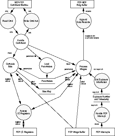
Figure 14 illustrates a simplified context diagram of the Front End Processor software.
FIGURE 14. Front End Processor Context Diagram
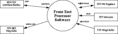
The interface between the Back End Processor and each of the Front End Processors is managed using shared-memory region residing on each FEP. The I/O library software running on a given FEP establishes and manages three interfaces with the Back End:
BEP-FEP Command Mailbox - This mailbox is used by the BEP to issue commands to the software running on a FEP, and to obtain the FEP's response to the command. This mailbox is primarily used by the BEP's FepIoManager class to load parameters, and start and stop bias and science activities on a FEP and to query FEP status.
FEP-BEP Ring-Buffer - This ring-buffer is used by a FEP to send large amounts of science data to the BEP. The data is organized into tagged data records, which are read by the BEP's FepIoManager class, subsequently parsed and processed by the BEP's Science Processing classes. A FEP primarily uses its ring-buffer to send exposure information records, and science data records, such as event records or histogram data records.
The I/O library software also provides low-level access functions to the Front End Processor hardware:
FEP Hardware Registers - Each FEP contains a set of hardware registers. These registers control the behavior of FEP's image acquisition and threshold hardware. The I/O library provides functions to read and write these registers. The BEP's FepDevice class access some of these registers across the shared-memory interface to reset the FEPs, and to determine the current reset state of the FEPs.
FEP Interrupts - Each FEP can be interrupted from a few sources. Its I/O library provides a common interrupt handler, which deals with all interrupt causes.
FEP Image Buffer - Each FEP contains a hardware-maintained image buffer, which is used to acquire CCD images for processing by the FEP software.
FEP Bias Map and Parity Plane (not shown) - Each FEP contains a hardware-maintained bias map buffer and parity plane, which is used by the FEP software to store CCD pixel bias values and verify the integrity of the bias map values. The BEP's FepIoManager class writes into this memory, via the shared memory interface, to mark bad pixels and columns. The BEP's BiasThief class reads from this memory when packing and telemetering the FEP's bias maps.
Figure 15 illustrates the overall data flow within the Front End Processors software. Shaded circles illustrate some of the services provided by the FEP Hardware and I/O library, and the unshaded circles illustrate the functions handled by the science processing functions.
The Science Processing functions perform three types of actions:
Load Parameters - This action is initiated by the Back End Processor, which passes parameters to each Front End using its Command Mailbox. The science software handles these commands between runs, storing the loaded parameters for use for the subsequent bias computations and data processing.
Compute Bias - The science software on a given Front End Processor is capable of computing the bias level for each CCD pixel represented in an image. This action is initiated via a command from the BEP. The type of bias to perform, and the parameters to use for the bias computation, are provided by a previous Load Parameters action. The resulting map of pixel-by-pixel bias values is retained for use by subsequent data processing. NOTE: Although it is not shown in the diagrams, the bias maps are located in shared memory, and are visible to the Back End Processor. This enables the BEP to telemeter the contents of the maps. Unfortunately, due to unforseen timing issues in the hardware, access to this area during data processing interferes with the hardware event processing. As a result, the BEP software only accesses this memory prior to starting event processing on the FEPs.
Process Images - The science software provides an action which processes incoming images from a CCD. The BEP initiates and terminates this action via the Command Mailboxes, specifying which mode to use when processing the images. The parameters to use for data processing are provided by a previous Load Parameters action, and the pixel bias values used are those computed by the most recent Compute Bias action.
FIGURE 15. Front End Processor Data Flow Diagram
This section provides an overview of the behavior of key features of the system.
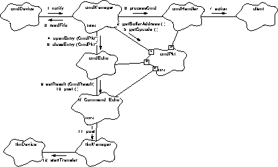
This section provides a simplified picture of how commands are received, executed, and responded to by the instrument software. For a detailed description of command reception and execution, see Section 16.0 and Section 17.0 .
In order to simplify the command system, the ACIS software is designed to handle one command at a time. As a result, commands must be received and executed as fast as they arrive at the instrument. ACIS is designed to handle no more than 4 commands per second. All commands must be processed in under 250ms.
The following object diagram shows the participants in handling a command, and a simplified sequence of actions which occur when the software processes a command. The numbered actions describe the main steps involved in processing commands sent to the instrument software.
FIGURE 16. Simplified Command Processing Object Diagram
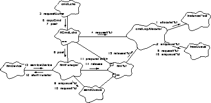
This section provides a simplified picture of how telemetry buffers are allocated, formatted, and sent out of the instrument. For a detailed description of telemetry management, buffer allocation and formatting, see Section 18.0 and Section 19.0 .
The ACIS software is required to produce many different types of telemetry item, at different rates, and merge these items into single telemetry stream, at either 24Kbps or 500bps. It is a goal of the ACIS software to avoid gaps in the telemetry stream whenever there is something to send. Since the RCTU transfers words at a rate of 128Kbps, and the telemetry hardware has 64 bits of buffering between the transfer hardware and the RCTU, the software must be capable of starting a new telemetry transfer within 0.5ms, in order to avoid padding between transferred packets.
The following object diagram shows an example of telemetry production and a simplified sequence of actions which occur when the software processes a single telemetry item. The numbered actions describe the main steps involved in producing a telemetry item. This particular scenario uses the cmdLog object, described above, as the starting point for illustrating the behavior of the telemetry system.
FIGURE 17. Simplified Telemetry Production Object Diagram
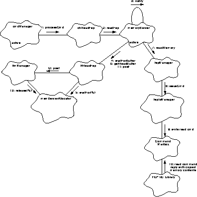
This section provides a simplified picture of how requests to dump portions of memory are handled. For a detailed description of memory dump services, and memory load and subroutine calling services, see Section 27.0 .
All memory functions are handled by a memoryServer object. In order to allow for large memory dumps, this object is implemented as a task. This object provides a set of binding functions, which may be safely called from other tasks to request services from the memoryServer, and a set of implementation functions, which are used by the memoryServer's task to implement the requested actions.
The following object diagram shows the participants in handling a request to dump the contents of a region of Front End Processor Memory.
FIGURE 18. Simplified Memory Dump Object Diagram
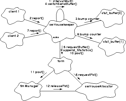
This section provides a simplified picture of how run-time statistics and conditions are acquired and posted to telemetry by the Back End software. For a detailed description of software housekeeping services, see Section 28.0 .
All statistics and warning conditions produced by the Back End Processor software are reported using a swHousekeeper object. In order to periodically telemeter the accumulated information, this object is implemented as task. This object provides a binding function, which other tasks use to report information.
The following object diagram shows how various software conditions are reported to housekeeping, and how this information is posted to telemetry.
FIGURE 19. Software Housekeeping Object Diagram
This section provides a simplified picture of how the instrument acquires housekeeping values from the Detector Electronics Assembly (DEA) and sends them to telemetry. For a detailed description of DEA housekeeping services, see Section 31.0 .
The ACIS software uses the deaHousekeeper task to acquire and telemeter housekeeping values from the Detector Electronics Assembly. Like other tasks in the system, the deaHousekeeper provides binding functions, which are used by other tasks to command the housekeeper to perform certain services.
The following object diagram shows how various DEA housekeeping classes are configured, and how housekeeping values are acquired and posted to telemetry.
FIGURE 20. DEA Housekeeping Runs Object Diagram
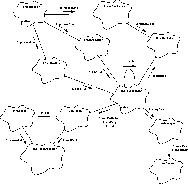
This section provides a simplified picture of how the instrument performs science data acquisition and processing runs. For a detailed description of science operations, see Section 33.0 , Section 37.0 , Section 42.0 , Section 43.0 , Section 44.0 and Section 45.0 .
Science processing is managed using a collection of related objects. The scienceManager object is a task which is responsible for coordinating the operation of a run. It provides binding functions which are used by other tasks to start and stop science runs.
The scienceManager object implements a particular science mode using a particular science mode object. The following example describes a Timed Exposure run, and uses an smTimedExposure object to implement the details of the run.
Any given science mode also has various processing modes. These are handled using a processing mode object. For a given run, one processing mode object is used to process the science data from one corresponding Front End Processor being used for the run. The example only illustrates one such object, pmEvent.
The following object diagram shows a simplified picture of the overall sequence of events which take place during a science run.
FIGURE 21. Science Run Object Diagram
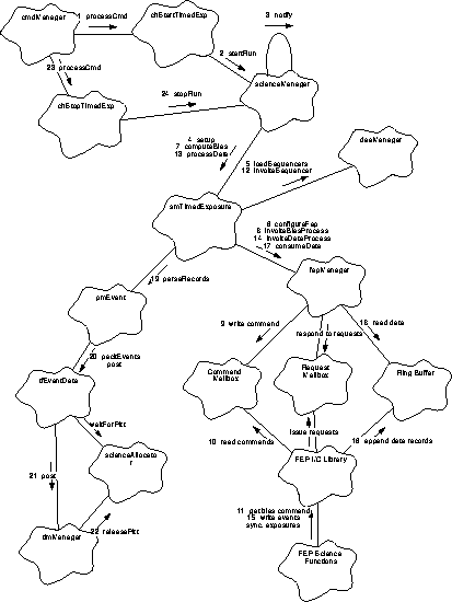
 TABLE 3. BEP Tasks
 Next Chapter