The quantum detection efficiency of the reference CCDs is obtained by alternately exposing the SSD and the CCD to the same source of X-rays, with the same restricting aperture defining the flux of photons that reaches each detector. The CCD is located such that all photons passing through the CCD aperture are incident on the CCD. The SSD actually uses a second aperture, almost identical to the first, which is moved into the same aperture position for the SSD measurements. This is accomplished by moving the SSD into and out of the X-ray beam with a stepper motor that translates the entire SSD assembly, with the re-entrant tube housing the Si(Li) crystal sliding through a vacuum flange with a double O-ring seal. The two apertures are attached to the SSD tube and move with it. The calibration geometry is shown in Figure 4. The stepper motor allows reproducible positioning of the SSD tube in one of three positions: SSD aligned with the beam axis, CCD illumination aperture aligned with the beam axis, and SSD tube fully retracted (to illuminate the entire CCD).
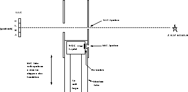
Figure 4: Schematic of calibration geometry used to compare CCD response to
that of the Si(Li) SSD.
Ideally, each of the four quadrants of the reference CCDs (denoted A,
B, C and D) would be calibrated separately, since there are four
output circuits. However, this should only affect the gain and noise
characteristics of each quadrant and not the detection efficiency.
Noise actually can affect detection efficiency indirectly by changing
the event grade classification probabilities, but this effect is small as long as
all four quadrants have comparable noise levels (which is typical).
Therefore a calibration measurement combining two or more quadrants is
acceptable, so long as all of the illumination spot remains on the
CCD. The calibration sources and apertures are therefore sized so that
the illuminated spot is entirely contained within two (for  Fe)
or three (all others) quadrants. By translating the CCD aperture the
calibration spot may be positioned at different locations across the
CCD, thereby allowing multiple measurements of CCD detection
efficiency relative to that of the SSD. These measurements allowed
for a check of uniformity across the CCD.
Fe)
or three (all others) quadrants. By translating the CCD aperture the
calibration spot may be positioned at different locations across the
CCD, thereby allowing multiple measurements of CCD detection
efficiency relative to that of the SSD. These measurements allowed
for a check of uniformity across the CCD.
For the  Fe measurements, the spot was centered on two quadrants at a
time, yielding three separate measurements denoted AB, BC and CD,
corresponding to the quadrants illuminated. For the other sources, three
quadrants were illuminated at once and the measurements are denoted ABC
and BCD. For each case, SSD data was taken with the SSD aperture
positioned in the same location as the CCD aperture was for CCD data.
The distance between the two holes was fixed and the stepper motor
was used to reproducibly move one or the other into the X-ray beam.
Fe measurements, the spot was centered on two quadrants at a
time, yielding three separate measurements denoted AB, BC and CD,
corresponding to the quadrants illuminated. For the other sources, three
quadrants were illuminated at once and the measurements are denoted ABC
and BCD. For each case, SSD data was taken with the SSD aperture
positioned in the same location as the CCD aperture was for CCD data.
The distance between the two holes was fixed and the stepper motor
was used to reproducibly move one or the other into the X-ray beam.
A second measurement technique, referred to as ALL, illuminated the entire CCD and relied on calculated solid angles to compare the CCD count rate to that of the SSD. Although this method is somewhat less accurate than the spot method due to both non-uniform illumination and to uncertainties in separation distances, it nonetheless provides a useful consistency check with the spot measurements.
The SSD external aperture with internal diameter 4.1 mm was placed immediately in front of and centered over the Be window to better define the detector acceptance area. The aperture was cut into an aluminum tube that slips over the stainless steel, with a nearly identical aperture located just beyond the end of the tube for illuminating the CCD. A larger exit aperture was also provided for the CCD optical path. These apertures are shown in Figure 4, which presents the overall calibration geometry. In addition to defining the active area of the detector, the aluminum aperture piece eliminates spurious fluorescence X-rays from the copper bias ring and stainless steel tube in the presence of high energy X-rays.
Care was taken to make the CCD and SSD apertures as nearly identical
as possible. The relative size of the two circular holes was
calibrated in two ways. First, a long exposure measurement was made
using the SSD and  Fe with each aperture centered over the Be
window. This yielded an open area ratio of 0.9972
Fe with each aperture centered over the Be
window. This yielded an open area ratio of 0.9972  , with
the SSD aperture being slightly larger. Secondly, measurements with a
scanning optical microscope revealed that the holes were reasonably
smooth, with edge features of order 30 microns or less. Diameter
readings obtained in this way indicated that the area ratio of the two
holes was 0.995
, with
the SSD aperture being slightly larger. Secondly, measurements with a
scanning optical microscope revealed that the holes were reasonably
smooth, with edge features of order 30 microns or less. Diameter
readings obtained in this way indicated that the area ratio of the two
holes was 0.995  , consistent with but less accurate than the
X-ray measurement.
, consistent with but less accurate than the
X-ray measurement.
An alignment tool with cross-hairs was used to position the SSD
aperture over the center of the Be window, and the location was
verified by monitoring the SSD count rate from a  Fe source before
and after the installation. The separation between the CCD and SSD
apertures and the corresponding stepper motor displacement was also
verified with the alignment tool.
Fe source before
and after the installation. The separation between the CCD and SSD
apertures and the corresponding stepper motor displacement was also
verified with the alignment tool.