Next: 4.3 XRCF Data Up: 4 Calibration/Maintenance Previous: 4.1.6 Sub-assembly Calibration Data
![]()
![]()
![]()
![]()

Next: 4.3 XRCF Data
Up: 4 Calibration/Maintenance
Previous: 4.1.6 Sub-assembly Calibration Data
 |
Transmissions for the ACIS pre-engineering, flight and backup OBFs have been obtained at the University of Wisconsin Synchrotron Radiation Center (SRC). The Multilayer Beamline there was ideally suited for these measurements due to its ability to access several energies in the 200-2000 eV range and its built-in, computer-controlled x-z stage, which allowed us to map the filter transmission automatically with excellent spatial resolution. See Townsley et al. Proc SPIE 134-145 (1996) for a description of the measurements and early results.
More than 30 filters were eventually measured at the SRC, including several which were repeatedly measured to search for contamination during testing and for ACIS camera contamination certification. (No change in transmission was ever detected during SRC tests, ruling out any significant contamination from this testing or from exposure of the filters to the ACIS camera.)
In the course of this testing it was found that the original filter substrate material (Lexan) could not be made taut enough to survive vibration testing without the formation of small pinwindows of aluminum flaking near the support structure. Accordingly the flight design was changed to use Polyimide, a similar plastic material with greater strength.
Also discovered during testing of the Lexan filters was the effect of using equal thickness alumimum coatings which induced Fabry-Perot-like interference transmission bands. These bands were narrow in wavelength, but high in transmission, so the thicknesses of the aluminum overcoats were made unequal to suppress these bands.
The final filter design consisted of a free-standing (i.e. no support mesh) membrane made of Polyimide (2000 Å thick) with an overcoat 300 Å of aluminum on one side, and 1000 Å (for the S filter) or 1300 Å (for the I filter) on the other side. The flight filters were mounted in the ACIS experiment at MIT, and were in place for the flight instrument calibration at XRCF during April and May, 1997.
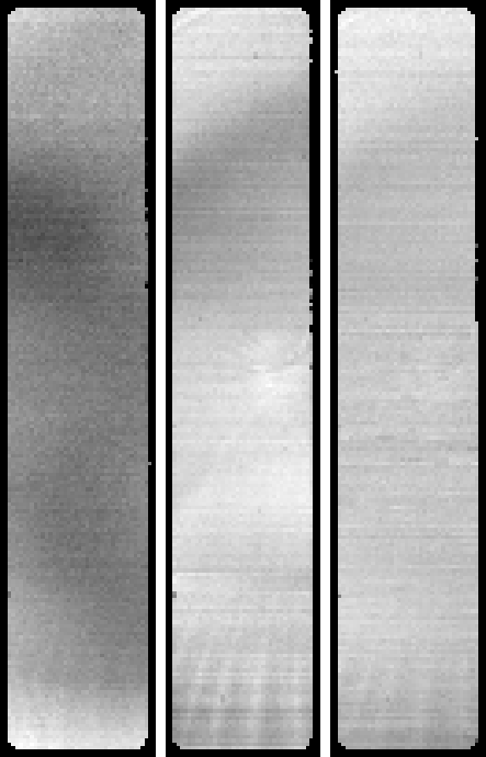
Each flight filter and backup unit was measured for X-ray transmission spatial uniformity at the SRC. The resulting transmission maps (see Figures 4.1 & 4.2) show filter performance meeting or exceeding the uniformity requirements. In the figures the gray-scale is set to show a full range from black to white of 2% of the median transmission at the energy displayed. Both flight filters (im009; left column in Fig. 4.1 and spec003; left column in Fig. 4.2) are outstanding, with little detectable variation above the noise level of 0.1%. (The horizontal bands are artifacts in the data and are not real.) The 273 eV data are most sensitive to variations in the aluminum overcoating; the 522 eV data are most sensitive to variations in the plastic substrate.
We obtained transmission measurements at five energies. Fitting these five points with a model of the filter transmission gave an agreement between model and data with a mean residual error of 0.34%. Each filter has been fit separately with similar results. The fit parameters for the flight filters are:
| (21) |
| (22) |
Witness sample filters and backup filters from the same batches used for the flight filters were taken to the Brookhaven National Laboratory (BNL) XC-08 synchrotron beamline for further testing. On this beamline several monochromators were used to provide thousands of energy measurements of transmission at two locations on each sample. See Chartas et al. Proc. SPIE 44-54 (1996) for a description of the measurement techniques and the transmission modelling.
Plots of the transmission for the ACIS-I and ACIS-S filters are shown in figures 4.3 and 4.4. Note the presence of strong absorption edges at 1.56 keV (aluminum K) and 284 eV (carbon K), and weaker features at 525 eV (oxygen K) and 400 eV (nitrogen K). The oscillatory behavior above the aluminum and carbon edges are due to EXAFS (extended X-ray absorption fine structure), and are real effects in the transmission. Chartas et al. ibid. discuss methodology for fitting these structures. Analysis continues for modelling the details of the transmission curves.
In addition to the SRC and BNL measurements, flight-like and witness samples were measured at Penn State in both optical and X-ray cold tests. Flight-like filters will also be measured at the SURF II synchrotron facility in Gaithersburg, MD, to measure the UV transmission curve versus energy. White-light tests were also conducted during the Lincoln Lab thermal-vacuum testing, the XRCF testing of the flight ACIS instrument, and stray light tests will be conducted at TRW during the integration of the flight instrument with the spacecraft.

John Nousek