 Table of Contents
  Previous Chapter
The ACIS Science Instrument Software (SIS) Fault Tolerance and Failure Modes Effects Analysis (FMEA) is derived from the ACIS System Failure Modes and Effects Analysis document. The System FMEA identifies and defines each hardware failure which the software must detect and manage.
Previous Chapter
The ACIS Science Instrument Software (SIS) Fault Tolerance and Failure Modes Effects Analysis (FMEA) is derived from the ACIS System Failure Modes and Effects Analysis document. The System FMEA identifies and defines each hardware failure which the software must detect and manage.
The following sections provide an overview of the software/hardware interfaces, a list of assumptions and ground rules in effect when performing the analysis, definitions of criticality levels and degrees of fault tolerance.
The remaining sections are grouped by hardware subsystem, as identified by the System FMEA. Each section contains a list of hardware failure definitions, with explanations as to how the failure is to be detected and reacted to by the software.
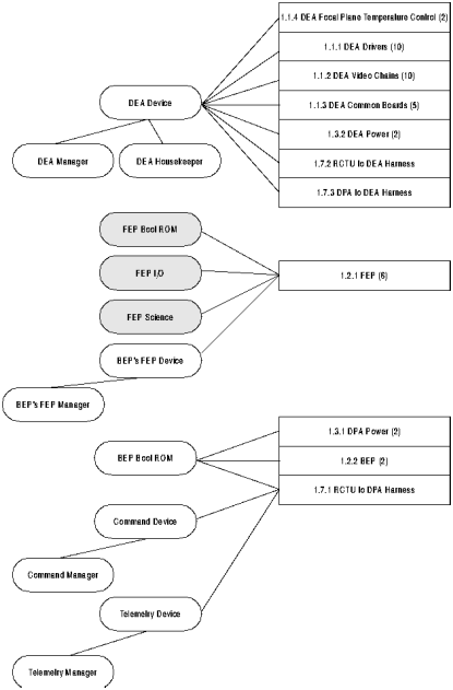
The ACIS SIS software is organized into layers. A single layer is devoted to the software hardware interfaces. Within this layer, each hardware interface, or group of related interfaces are managed by a single software unit. Figure 1 illustrates the software/hardware interfaces and assigns primary responsibility of the interface to one or more software units. The hardware elements are specified down to the level identified in the System FMEA. At this level of granularity, several software elements may be responsible for a single System-level hardware element. Hardware which does not affect a hardware/software interface is not shown. In the figure, boxes represent a hardware element as identified in the System FMEA, ovals represent a software unit, lines between a hardware element and software unit indicate a direct hardware/software interface, and lines between software units represent cases where a software unit has indirect connections to the hardware subsystem and may have fault detection/management responsibilities. Shaded ovals represent software which executes on the Front End Processors. All other indicated software executes on the Back End Processor.
FIGURE 1. Hardware/Software Interface Block Diagram
This section lists the assumptions and ground rules in effect during this analysis.
1. The system design ensures that the software cannot damage the science instrument or crew by issuing any hardware command or by not responding in time to a hardware condition.
2. The system design ensures that the software cannot exhaust any consumable resource (such as power) by issuing any hardware command or by not responding in time to a hardware condition.
3. All analysis will performed as a result of failure conditions specified in the ACIS System FMEA. Other types of failures will not be addressed in this document.
This section lists the criticality levels, as defined in MM8075.1 Section 2.2.2.7.2.c:
- Criticality 1 (C1) - Crew Safety. A failure which can result in the loss of system, system element, or flight/ground crew.
- Criticality 2 (C2) -Mission Critical. A failure which can result in the loss or suspension of mission operational capability.
- Criticality 3 (C3) - Mission Support. All other kinds of failures.
Given the assumptions listed in Section 2.2, all failures described in this document have a level of Criticality 3. At worst, any single fault specified in this document may result in the loss of part of the science data.
This section lists the fault tolerance levels, as defined in MM8075.1, Section 2.2.2.7.2.d:
- F0 - No fault tolerance provided by the software.
- F1 - One level of fault tolerance provided by the software. The software element is capable of sustaining a single fault.
- FM - Multiple levels of fault tolerance provided by the software. The software element is capable of sustaining multiple faults.
Table of Contents  Next Chapter