 Table of Contents
 Previous Chapter
 Table of Contents
 Previous Chapter
The fepSciCClk module, executing in the FEP, implements continuously clocked science processing, comprising either raw mode or event detection mode. It is called from fepCtl with a single argument, fp, a pointer to the fepParm structure. Before invoking fepSciCClk, the FEP must be commanded to (a) load a continuous clocking FEPparmBlock into fp->tp, and (b) perform a continuous clocking bias calibration.
The fepSciCClk function operates in one of the following modes, according to the value of fp->tp.type:
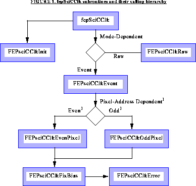
FIGURE 178. fepSciCClk subroutines and their calling hierarchy

All interactions with the BEP and with FEP hardware are made through fepio library functions described in Section 38.0. The data structures that are passed between FEP and BEP are defined in that document and in Section 4.10. fepSciCClk makes use of the following functions which call each other in the manner shown in Figure :
FEPparmBlock, fp->tp, and performs all necessary mode-dependent initialization, e.g. in event-finding mode, it checks that the bias map has been initialized.
FEPeventRecRaw records without any thresholding, as shown in the shaded region of Figure 179.
FEPeventRec1x3 record to the ring buffer.
FEPeventRec1x3 record to the ring buffer.
inline function (and therefore not shown in Figure ) that is called several times within FEPsciCClkEvenPixel and FEPsciCClkOddPixel to determine whether the central pixel is less than (or equal to) one of its neighbors.
FEPerrorRec record to the ring buffer, and returns to the caller the corrected value of the bias map pair.
The following FEPparm fields, defined in fepCtl.h and invariably addressed by
the fp pointer parameter, are used by all continuously clocked modes:
brcolshftFEPexpRec record
- bias0
[4]- dOclk
FEPexpEndRec record
- expnum
- parityerrs
- thresholds
FP_SUSPENDBEP_FEP_CMD_SUSPEND
FP_TERMINATEBEP_FEP_CMD_STOP
- image
- thresh
- type
The following paragraphs describe the basic functions performed in continuously clocked mode. All Continuous Clocking modes wait until an image frame (a block of DEA output pixels delimited by VSYNC flags, typically comprising 512 image rows) is processed and copied to the ring buffer before commanding the hardware thresholder to read the next frame, thereby ensuring that no partial frames are generated.
FEP_CCLK_PARM_1x3. After calling FEPsciCClkInit to check that the bias array contains appropriate values and to load the hardware registers, FEPsciCClk calls fepEnableNextFrame and waits for the first 512-row frame to arrive.
FEPexpRec structure and calls fepAppendRingBuf to copy it to the ring buffer. It then calls FEPsciCClkEvent to process the frame.
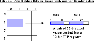
[], indexed by their DEA output nodes. It then inspects the T-plane buffer and calls either FEPsciCClkEvenPixel or FEPsciCClkOddPixel whenever a non-zero bit is found, indicating that the thresholder has located a pixel that exceeds its bias value by fp->tp.thresh[nn], where nn is the index of the appropriate DEA output node. Since the 12-bit pixel and bias values are only accessible two at a time via 32-bit CPU instructions, the logic required to inspect even-indexed pixels differs considerably from that needed for odd-indexed pixels, hence the two separate routines.
FIGURE 180. The Relation Between Image Pixels and FEP Register Values

FEPeventRec1x3 record.
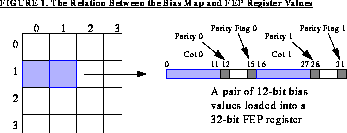
FIGURE 181. The Relation Between the Bias Map and FEP Register Values

[] values and calls FIOsetThresholdRegister to update the hardware threshold registers.
FEPexpEndRec (end-of-frame) record to the ring buffer.
FEP_CCLK_PARM_RAW. It begins in an identical manner to the event-finding modes described in the previous sections, except that fepSciCClk calls FEPsciCClkRaw to process each 512-row frame.
FEPeventRecRaw record and thence to the ring buffer.
This section describes the functions that are local to the fepSciCClk unit. The only external is fepSciCClk itself which is called from fepCtl. The FEPparm structure is defined in fepCtl.h, along with several pixel access macros. The interface to the FEP I/O library is described in Section 38.0, and data and messages exchanged between FEP and BEP are described in Section 4.10.
FEPparm *fp
fepSciCClk is called from fepCtl with a single argument: the pointer fp to
the fepParm structure. It is responsible for all FEP actions associated with a
timed exposure science run, except for bias calibration. In particular, it controls the
double-buffering of input data---the image map is split logically into two 512-row
buffers and the FEP hardware is told to write into one while the software is pro
cessing the other. fepSciCClk performs the following actions:
i)  Calls FEPsciCClkInit to validate the BEP's parameter block, fp->tp,
for the current mode, to verify that pixel biases have been computed, and to
initialize mode-dependent variables. If FEPsciCClkInit returns
FEP_CMD_NOERR, fepSciTimed calls fepAckCmd and continues. Oth
erwise, it calls fepNackCmd to pass the fepCmdRetCode error code to
the BEP, indicating that the command has failed, and fepSciCClk then re
turns to fepCtl. Error codes are defined in fepBep.h (see Section 4.10).
ii)  Calls fepEnableNextFrame to enable the hardware to read the first 512
rows of image pixels into the image buffer.
iii)  Loops over frames of 512 rows of image pixels.
fp->nextexpnum is encountered (or exceeded). During this loop, calls are made to FIOgetNextCmd to handle any incoming BEP commands, and to FIOtouchWatchdog to prevent the Watchdog Timer from expiring while waiting for that particular frame. FP_TERMINATE bit is set, fepSciCClk returns immediately---the science run is over; if the FP_SUSPEND bit is set, fepSciCClk loops until the BEP sends it a BEP_FEP_CMD_RESUME command.
BEP_FEP_CMD_STOP command from the BEP, which sets the FP_TERMINATE bit in fp->flags. fepSciCClk will finish processing the current frame before returning to fepCtl.
FEPparm *fp
This function is called from fepSciCClk to verify the contents of the FEPparmBlock, fp->tp, and to check whether a bias calibration has been per formed. It also performs any necessary mode-dependent initialization. The follow ing fp->tp and fp->br fields are checked:---------------------------------------------------- Tests Error code returned Applied if the test fails ---------------------------------------------------- quadcode &OE; fepQuadCodeIf an error is detected, FEPsciCClkInit returns the appropriate fepCmdRet Code value, as defined in fepBep.h (see Section 4.10); otherwise it returns FEP_CMD_NOERR.FEP_CMD_ERR_QUAD_CODE0 < nrows £ CCLK_NROWSFEP_CMD_ERR_NROWS0 < ncols, and ncols evenFEP_CMD_ERR_NCOLSquadrants * ncols £ MAX_NCOLSFEP_CMD_ERR_NCOLSnoclk £ MAX_NOCLKFEP_CMD_ERR_NOCLK(fig)FEP_CMD_ERR_NO_BIAS----------------------------------------------------
FEPparm *fp
This function is called from fepSciCClk to process a single continuously
clocked frame. It initializes the following row pointers to the addresses of data
structures used by the hardware thresholder:
unsigned irow
unsigned icol
FEPparm *fp
This function is called from FEPsciCClkEvent for every bit set in the T-plane
whose bit offset is even. The associated pixel is located in row irow, column
icol, and fp->image points to the first pair of pixels in that row. The corre
sponding pair of bias values are to be found in fp->image[BIAS_OFFSET].
FEPsciCClkEvenPixel first loads the 32-bit pixel and bias fields that contain
the central pixel. Since the FEP is a little-endian processor, and the central pixel is
stored in the lower address pair of bytes, pixel and bias will be loaded into the least-
significant 16 bits of each 32-bit variable. (The most significant 16 bits of these
variables will contain the pixel and bias for row irow and column icol+1.)
The pair of bias values is now validated---the bias parity flags (bits 15 and 31) are
tested to determine whether a parity error has occurred in either of those locations
in the bias map. If so, a call is made to FEPsciCClkFixBias to handle the
problem, and the corrected 32-bit bias pair is written back to the bias map. Unlike
the situation in timed exposure mode, when the software is merely able to report
the damaged pixel, in continuous clocking mode the value can actually be repaired
since each row of the bias map should be identical. Therefore, once the bias value
has been updated, FEPsciCClkEvenPixel continues execution with the cor
rected value.
Next, a test is made to determine whether this central pixel lies on the left- or right-
hand edge of the CCD, or if its bias value is PIXEL_BAD (indicating that the pixel
is a member of the bad-pixel list). In any of these situations, the pixel is ignored.

The 12-bit value of the central pixel is saved in ev.p[1] of a local
FEPeventRec1x3 structure, and the corresponding 12-bit bias value in
ev.b[1]. To assist in later FEPsciCClkPixTest calls, the variable val is set
equal to the difference between the center pixel value and its bias values, as dis
cussed in Section 43.6.6.
The center pixel is now compared to those lying to its left and right, using
FEPsciCClkPixTest, which also saves the pixel and bias values in the appro
priate elements of the ev.p and ev.b arrays. If a test fails, i.e. if the central pixel
isn't a local maximum, the function returns. When testing the pixel lying to the left,
val must be adjusted for any change in average overclock if the two pixels were
generated by different CCD output nodes. This change is simply the difference be
tween the corresponding node values in the fp->ex.dOclk[] array.
If the pixels on either side of the central pixel survive the FEPsciCClkPixTest
criteria, the 1x3 pixel and bias arrays in the ev structure will have been loaded.
FEPtestEvenPixel then calls fepAppendRingBuf to write the
FEPeventRec1x3 record to the FEP-BEP ring buffer.
unsigned irow
unsigned icol
FEPparm *fp
This function is called from FEPsciCClkEvent for every bit set in the T-plane
whose bit offset is odd. The associated pixel is located in row irow, column
icol, and fp->image points to the first pair of pixels in that row. The corre
sponding pair of bias values are to be found in fp->image[BIAS_OFFSET].
FEPsciCClkOddPixel first loads the 32-bit pixel and bias fields that contain
the central pixel. Since the FEP is a little-endian processor, and the central pixel is
stored in the upper address pair of bytes, pixel and bias will be loaded into the
most-significant 16 bits of each 32-bit variable. (The least significant 16 bits of
these variables will contain the pixel and bias for row irow and column icol1.)
The pair of bias values is now validated---the bias parity flags (bits 15 and 31) are
tested to determine whether a parity error has occurred in either of those locations
in the bias map. If so, a call is made to FEPsciCClkFixBias to handle the
problem, the corrected 32-bit bias pair is written back to the bias map. Unlike the
situation in timed exposure mode, when the software is merely able to report the
damaged pixel, in continuous clocking mode the value can actually be repaired
since each row of the bias map should be identical. Therefore, once the bias value
has been updated, FEPsciCClkOddPixel continues execution with the cor
rected value.
Next, a test is made to determine whether this central pixel lies on the left- or right-
hand edge of the CCD, or if its bias value is PIXEL_BAD (indicating that the pixel
is a member of the bad-pixel list). In any of these situations, the pixel is ignored.

The 12-bit value of the central pixel is saved in ev.p[1] of a local
FEPeventRec1x3 structure, and the corresponding 12-bit bias value in
ev.b[1]. To assist in later FEPsciCClkPixTest calls, the variable val is set
equal to the difference between the center pixel value and its bias value, as dis
cussed in Section 43.6.6.
The center pixel is now compared to those lying to its left and right, using
FEPsciCClkPixTest, which also saves the pixel and bias values in the appro
priate elements of the ev.p and ev.b arrays. If a test fails, i.e. if the central pixel
isn't a local maximum, the function returns. When testing the pixel lying to the
right, val must be adjusted for any change in average overclock if the two pixels
were generated by different CCD output nodes. This change is simply the differ
ence between the corresponding node values in the fp->ex.dOclk[] array.
If the pixels on either side of the central pixel survive the FEPsciCClkPixTest
criteria, the 1x3 pixel and bias arrays in the ev structure will have been loaded.
FEPsciCClkOddPixel then calls fepAppendRingBuf to write the
FEPeventRec1x3 record to the FEP-BEP ring buffer.
FEPeventRec1x3 *ev
unsigned dcol
unsigned val
unsigned pixel
unsigned code
unsigned bias
This is an inline function that is used several times within the
FEPsciCClkEvenPixel and FEPsciCClkOddPixel functions. It masks
the 12 low-order bits of pixel and bias and stores them in p[dcol] and
b[dcol] in the ev structure. It then compares the value of (pixel - bias)
against val.
FEPsciCClkPixTest evaluates to TRUE when the value of the pixel at dcol
is inconsistent with a legal event, or FALSE when it isn't. Illegal events are those
for which the corresponding bias value is PIXEL_BAD, i.e . when the correspond
ing pixel is a member of the bad column list, or those that pass the test defined by
the mode parameter, which is either LE ("less-than-or-equal"), in which an illegal
pixel satisfies
val <= (pixel - bias)
or LT ("less than"), when an illegal pixel satisfies
val < (pixel - bias)
dcol must be in the range 0-2; the "center" pixel has dcol=1; dcol=0 refers
to the column before the center pixel, dcol=2 to the column after. Constants
PIXEL_MASK, and PIXEL_BAD are defined within fepCtl.h, and val and ev are
local variables.
unsigned bias
unsigned irow
unsigned icol
FEPparm *fp
This function is called from FEPsciCClkEvenPixel or FEPsciCClkOd
dPixel, when a parity error is detected in either or both of the halves of a 32-bit
bias word. Each corrupted 12-bit value is replaced by the first non-corrupted val
ue in the same column icol of the bias map, and FEPsciTimedError is called
(twice if both 12-bit values are bad) to reset the appropriate bits in the Bias Parity
Plane and T-plane. It then calls fepAppendRingBuf to send a message of type
FEP_ERROR_REC to the BEP containing irow, icol, the uncorrected bias
value, and the current exposure number in fp->ex.expnum. Finally,
FEPsciCClkFixBias returns the fixed-up 32-bit bias word to the caller,
which has the responsibility for saving it back in the appropriate location in the
bias map. NOTE: since bias represents a pair of values, icol must necessarily
be even.
unsigned val
unsigned irow
unsigned icol
FEPparm *fp
This function is called from FEPsciCClkFixBias when a parity error is detect
ed in row irow, column icol of the bias map. It computes the parity of the 12-
bit bias value, val, and resets the relevant bit in the Bias Parity Plane, turns off the
corresponding bit in the T-plane, and increments the bias error counter,

fp->exend.parityerrs.
FEPparm *fp
This function is called from fepSciCClk to process a single raw CCD frame. It
initializes the following pointers to the addresses of data structures used by the
hardware thresholder: