 Table of Contents
 Previous Chapter
ACIS
This section describes the overall architecture of the ACIS Science Instrument Software, and identifies the key interfaces between the hardware and the software, and between the major software components.
The bulk of the ACIS Science Instrument Software resides in the Back End Processor. This software is responsible for managing commands and telemetry, and for filtering and packing science data. The design of the BEP software utilizes object-oriented design techniques, and uses a commercial real-time multi-tasking executive.
The FEP software is responsible for processing raw pixel data as quickly as possible. In general, this software has to deal with only one task at a time. As a result, the design of this software operates using a simple interrupt handler and single main thread of control, and takes a structured design approach.
Class categories are a way of grouping related classes. In the ACIS design, there are five main categories:
- Devices - These classes deal with the physical ACIS hardware
- Executive - These classes provide an interface to the underlying real-time executive
- Protocols - These classes deal with externally imposed protocols, such as command packet formats, telemetry formats, etc.
- Applications - These classes deal with the implementation of the core system requirements, such as performing a science mode, or dumping the contents of memory.
- Utilities - These are classes which do not easily fit into one of the above categories. Typically, these classes are globally accessible. NOTE: We have not yet defined any classes which occupy this category. Most such classes have found appropriate homes in one of the class categories listed above. If this condition persists, this category of classes will be removed from the design.
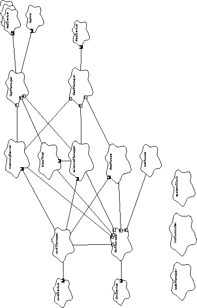
This section identifies the global system objects within ACIS. Figure 3, "BEP Global System Objects," on page 56 illustrates the key higher level global objects within the ACIS software. In that figure, the solid-lined "clouds" represent objects, and the connecting lines show who is talking to whom. The filled boxes indicate that the object is exclusively used by the party at the other end of the line. The empty boxes indicate that the adjacent object is shared by several other objects.
FIGURE 3. BEP Global System Objects
Devices
cmdDevice - This object is responsible for physically reading
command packets from the BEP's command hardware.
tlmDevice - This object is responsible for setting up the teleme
try hardware to transfer the contents of a region of memory to the
RCTU serial telemetry port.
deaDevice - This object is responsible for writing commands to
the DEA command port, and for reading status words from its reply
port.
fepDevice[6] - Each object corresponds to a single FEP. These
objects are responsible for accessing the FEP control hardware and
for accessing memory-mapped hardware and software mailbox
locations within the corresponding FEP.
fepIntrDevice - This object is responsible for providing access
to the single FEP to BEP interrupt shared by all of the FEPs.
Protocols
cmdManager - This object is responsible for acquiring commands
from the cmdDevice and executing the commands. It uses the
tlmManager, via a cmdLog object (not shown), to acknowledge
the reception of the commands and indicate its disposition.
tlmManager - This object is responsible for queueing telemetry
transfer requests from the many telemetry sources within the sys
tem. The tlmManager uses the tlmDevice to instruct the hard
ware to physically transfer the telemetry items.
deaManager - This object is responsible for formatting and send
ing commands to the Detector Electronics Assembly, and for pro
cessing any acquired status information and data. This object uses
the deaDevice to issue command and retrieve responses from the
physical DEA hardware.
fepManager - This object is responsible for commanding the
FEPs and for managing data being produced by the FEPs. This
object uses all of the fepDevices to send and receive informa
tion from the individual FEPs and uses the fepIntrDevice to
manage the shared interrupt.
fepIoManager[6] (not shown) - These 6 objects are responsible
for managing the I/O protocol to and from each of the Front End
Processors. Each manager corresponds to a single FEP.
Applications
memoryServer - This object is responsible for performing mem
ory dumps, run-time memory loads, and commanded function calls.
It uses the fepManager to forward such requests to the FEPs, the
deaManager to perform DEA memory loads and dumps. The
memoryServer uses the tlmManager to transfer memory
dumps and the return values from function calls into telemetry.
scienceManager - This object is responsible for managing sci
ence data production, acquisition, and processing. It uses the dea
Manager to load and command the DEAs to clock the CCDs. It
uses the fepManager to acquire the resulting science data. This
object uses the tlmManager to place the produced science data
into the telemetry stream.
deaHouse - This object is responsible for acquiring and sending
DEA engineering data to telemetry. It uses the deaManager to
request and acquire specific housekeeping values from the DEA,
and it uses the tlmManager to place the acquired housekeeping
data into the telemetry stream.
swHouse - This object is responsible for accumulating and report
ing various software housekeeping statistics. It uses the tlmMan
ager to place the acquired data into the telemetry stream. Just
about every object in the system may report information to this
object.
biasThief - This object acts under the direction of the
scienceManager, and is responsible for acquiring and sending
bias map data from the Front End Processors as telemetry and pro
cessing resources permit.
General Purpose
taskManager - This object is responsible for coordinating the
activities of all of the tasks within the BEP. This object has indirect
access to every task within the BEP (not shown).
intrController - This object is responsible for managing
interrupts within the BEP. It has access to every interruptible
devices within the BEP, and provides interrupt enable/disable ser
vices to the rest of the BEP software.
systemClock - This object is responsible for providing the cur
rent time, in units of BEP timer-ticks, to the other objects within the
BEP.
In addition to the objects described above, the Back End Processor also uses a variety of global low-level hardware interface objects to manage access to the Back End's CPU and the attached hardware. These include the following:
mongoose - This object is responsible for coordinating access to
the R3000 System Coprocessor register and to the Mongoose Com
mand/Status Interface (CSI) registers.
bepReg - This object is responsible for coordinating access to the
Back End Processor's Control, Status and Pulse hardware registers,
and providing access to the Command FIFO, Downlink Transfer
Control, and the Detector Electronics Assembly Command, Status
and Microsecond Timestamp registers.
dmaDevice - This object is responsible for managing transfers
using Mongoose's Direct Memory Access (DMA) device.
timerDevice - This object is responsible for managing the Mon
goose's General-Purpose Timer device.
watchdogDevice - This object is responsible for managing the
Mongoose's Watchdog Timer device.
Within ACIS, there are six Front End Processors (FEP), each acting under the direction of the Back End Processor (BEP). During a given run, each FEP is responsible for processing images from one CCD.
This section summarizes the architecture of the software running on each of the Front End Processors. This software consists of two main types:
- Science Processing Functions
- Hardware and I/O Library
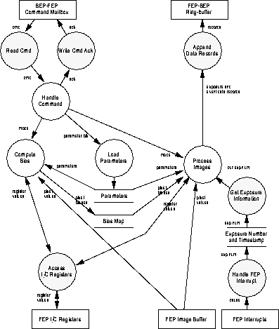
Figure 4 illustrates a simplified context diagram of the Front End Processor software.
FIGURE 4. Front End Processor Context Diagram

The interface between the Back End Processor and each of the Front End Processors is managed using shared-memory region residing on each FEP. The I/O library software running on a given FEP establishes and manages three interfaces with the Back End:
BEP-FEP Command Mailbox - This mailbox is used by the BEP to issue commands to the software running on a FEP, and to obtain the FEP's response to the command. This mailbox is primarily used by the BEP to load parameters, and start and stop bias and science activities on a FEP.
FEP-BEP Request Mailbox - This mailbox is used by a FEP to issue requests to the Back End, and to obtain the BEP's response to the request. A FEP primarily uses this mailbox to inform the BEP when a bias computation is complete, and to synchronize with the BEP at the end of each exposure.
FEP-BEP Ring-Buffer - This ring-buffer is used by a FEP to send large amounts of science data to the BEP. The data is organized into tagged data records, which are subsequently parsed and processed by the BEP. A FEP primarily uses a ring-buffer to send exposure information records, and science data records, such as event records or histogram data records.
The I/O library software also provides low-level access functions to the Front End Processor hardware:
FEP Hardware Registers - Each FEP contains a set of hardware registers. These registers control the behavior of FEP's image acquisition and threshold hardware. The I/O library provides functions to read and write these registers.
FEP Interrupts - Each FEP can be interrupted from a few sources. Its I/O library provides a common interrupt handler, which deals with all interrupt causes.
FEP Image Buffer - Each FEP contains a hardware-maintained image buffer, which is used to acquire CCD images for processing by the FEP software.
Figure 5 illustrates the overall data flow within the Front End Processors software. Shaded circles illustrate some of the services provided by the FEP Hardware and I/O library, and the unshaded circles illustrate the functions handled by the science processing functions.
The Science Processing functions perform three types of actions:
Load Parameters - This action is initiated by the Back End Processor, which passes parameters to each Front End using its Command Mailbox. The science software handles these commands between runs, storing the loaded parameters for use for the subsequent bias computations and data processing.
Compute Bias - The science software on a given Front End Processor is capable of computing the bias level for each CCD pixel represented in an image. This action is initiated via a command from the BEP. The type of bias to perform, and the parameters to use for the bias computation are provided by a previous Load Parameters action. The resulting map of pixel-by-pixel bias values is retained for use by subsequent data processing. NOTE: Although it is not shown in the diagrams, the bias maps are located in shared memory, and are visible to the Back End Processor. This enables the BEP to telemeter the contents of the maps without interfering with data processing activities on the FEPs.
Process Images - The science software provides an action which processes incoming images from a CCD. The BEP initiates and terminates this action via the Command Mailboxes, specifying which mode to use when processing the images. The parameters to use for data processing are provided by a previous Load Parameters action, and the pixel bias values used are those computed by the most recent Compute Bias action.
FIGURE 5. Front End Processor Data Flow Diagram
This section provides an overview of behavior of key features of the system.
This section provides a simplified picture of how commands are received, executed, and responded to by the instrument software. For a detailed description of command reception, and execution, see Section 16.0 , Section 17.0 and Section TBD.
In order to simplify the command system, the ACIS software is designed to handle one command at a time. As a result, commands must be received and executed as fast as they arrive at the instrument. At this time, ACIS is expected to handle no more than 4 commands per second. All commands will be processed in under 250ms (NOTE: If needed, exceptions to this will be allowed prior to test, but such exceptions must be clearly documented in the as-built Detailed Design Specification and Operators Manual).
The following object diagram shows the participants in handling a command, and a simplified sequence of actions which occur when the software processes a command. The numbered actions describe the main steps involved in processing commands sent to the instrument software.
FIGURE 6. Simplified Command Processing Object Diagram
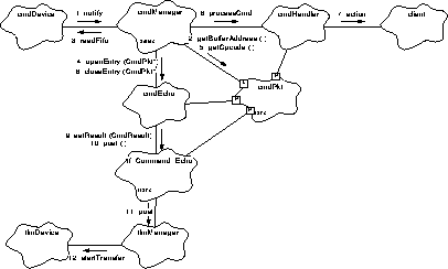
- A command packet is received by the Back End's RCTU interface hardware, which stores the packet words into a hardware FIFO. Once the entire packet has been received, the hardware generates an interrupt. The interrupt controller dispatches control to the cmdDevice object, which notifies the cmdManager task object that a command is ready.
- The cmdManager establishes a transient cmdPkt object, used to hold the contents of the command packet, and copies the command packet data from the FIFO into cmdPkt's data buffer, using the cmdDevice's function, readFifo().
- The cmdManager tells the cmdLog to establish an entry for the new command, passing a pointer to the temporary cmdPkt.
- The cmdLog establishes a transient tfCmdEcho object, used to format and telemeter a copy of a command packet, and instructs the object to copy the contents of the command packet into its telemetry buffer.
- The cmdLog tells the completed object to post its telemetry buffer for transfer out of the instrument.
- The tfCmdEcho object then passes its buffer to the tlmManager object, which queues the buffer for transfer out of the instrument.
- Eventually, the tlmManager instructs the tlmDevice object to transfer the buffer's contents to the RCTU telemetry interface hardware.
- Meanwhile, the cmdManager uses the opcode, contained within the received command packet, to select one of many cmdHandler objects. The cmdManager tells the selected cmdHandler to execute the received command.
- The cmdHandler object interprets the contents of the command, and invokes any warranted client object actions.
- Once the command has been executed by the cmdHandler, the cmdManager tells the cmdLog to close the entry for the current command, passing it the result of the command execution. At this point, the transient cmdPkt object can be destroyed.
This section provides a simplified picture of how telemetry buffers are allocated, formatted, and sent out of the instrument. For a detailed description of telemetry management, buffer allocation and formatting, see Section 18.0 and Section 19.0 .
The ACIS software is required to produce many different types of telemetry items, at different rates, and merge these items into single telemetry stream, at either 24Kbps or 500bps. It is a goal of the ACIS software to avoid gaps in the telemetry stream whenever there is something to send. Since the RCTU transfers words at a rate of 128Kbps, and the telemetry hardware has 64 bits of buffering between the transfer hardware and the RCTU, the software should be capable of starting a new telemetry transfer within 0.5ms, in order to avoid gaps between transferred packets.
The following object diagram shows an example of telemetry production and a simplified sequence of actions which occur when the software processes a single telemetry item. The numbered actions describe the main steps involved in producing a telemetry item. This particular scenario uses the cmdLog object, described above, as the starting point for illustrating the behavior of the telemetry system.
FIGURE 7. Simplified Telemetry Production Object Diagram
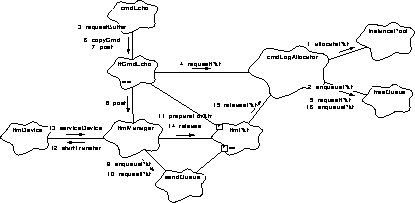
- During system initialization, each telemetry buffer allocator object, including cmdLogAllocator, initializes itsrespective pools of telemetry packet buffers and free queues. Each then proceeds to allocate every packet in its pool, instancePool. Buffer pools are used instead of fixed size arrays of telemetry packet buffers in order to allow easier patching of the number and size of different types of telemetry packets. NOTE: In order to keep different parts of the system reasonably de-coupled, they use different allocators. This way, if one part of the system consumes all of their telemetry buffers, another part may still be able to send data. If a single allocator were used, then any one part of the system could repeatedly consume all available telemetry buffers, denying the rest of the system the ability to send information.
- Continuing their initialization, the allocator objects add pointers to the allocated buffers into their respective freeQueue's. Once all buffers have been allocated from their pools and placed into the appropriate freeQueue, the buffer initialization is complete.
- Later, in response to an incoming command, the cmdLog is told to open a log entry by the cmdManager (see Figure 6). As part of its Verbose Mode processing, the cmdLog declares a tfCmdEcho object, and tells the object to obtain a telemetry packet buffer.
- The tfCmdEcho object asks cmdLogAllocator, the telemetry buffer allocator object used to provide command log and echo telemetry buffers, to obtain a telemetry packet buffer.
- cmdLogAllocator goes to its freeQueue and removes a packet buffer from the queue.
- Once tfCmdEcho gets a buffer, tlmPkt, from the allocator, the cmdLog tells tfCmdEcho to copy the command packet contents into the telemetry buffer.
- cmdLog then tells tfCmdEcho to post its buffer to the telemetry manager.
- tfCmdEcho, in turn, passes tlmPkt to the tlmManager.
- tlmManager appends a pointer to the packet into its sendQueue.
- Later, once all packets ahead of tlmPkt have been transferred out of the instrument, tlmManager removes tlmPkt from the front of the sendQueue.
- tlmManager then prepares tlmPkt for transfer out of the instrument, obtaining its raw buffer address and the number of words to transfer from tlmPkt.
- tlmManager tells the tlmDevice to transfer the buffer out of the instrument. tlmDevice then programs the Back End's telemetry interface hardware to supply data from the specified buffer to the RCTU serial telemetry port.
- Once the requested number of words have been transferred from the BEP to the RCTU interface, the hardware generates a telemetry interrupt. At this point, the software has a minimum of 0.5ms to program the telemetry hardware to handle a new transfer before a fill-pattern byte is written to the RCTU by the hardware. The tlmDevice's interrupt handler calls the tlmManager directly to service the device.
- tlmManager tells the tlmPkt that it is free to be reused. It then attempts to get the next packet from its sendQueue and start the next transfer if another packet buffer is ready to be sent (not shown).
- tlmPkt then tells its allocator, cmdLogAllocator, to release it.
- cmdLogAllocator then places tlmPkt's address back into its freeQueue. tlmPkt is now ready to be re-used.
This section provides a simplified picture of how requests to dump portions of memory are handled. For a detailed description of memory dump services, and additionally, memory load and subroutine calling services, see Section 27.0 .
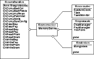
All memory functions are handled by a memoryServer object. In order to allow for large memory dumps, this object is implemented as task. This object provides a set of binding functions, which may be called safely from other tasks to request services from the memoryServer, and a set of implementation functions, which are used by the memoryServer's task to implement the requested actions.
The following object diagram shows the participants in handling a request to dump the contents a region of Front End Processor Memory.
FIGURE 8. Simplified Memory Dump Object Diagram
- The cmdManager receives a command packet instructing the system to dump a portion of one of the Front End Processor's memory. It looks up the corresponding handler object, chReadFep, and instructs it to process the command.
- The chReadFep object interprets the contents of the command packet, checking and extracting the index of the FEP from which to read, from which address, and how many words to send. chReadFep then tells the memoryServer object to perform the read using a binding function provided by the memoryServer.
- The memoryServer's binding function then notifies the task that a request has been registered. Once the request has been registered, the binding function returns to chReadFep, which then returns the result of the request to the cmdManager object. The cmdManager then logs the result with the cmdLog, as shown in Figure 6. Note that the time it takes to execute steps 1 - 3 must take less than 250ms.
- Later, the memoryServer's task wakes up due to the notification, and proceeds to perform the requested memory dump. It starts by declaring a tfReadFep object, which is used to manage and format the telemetry packet buffer containing the dumped data, and telling the object to wait for a telemetry packet buffer to become available.
- The tfReadFep object uses the allocator dedicated to the memoryServer, memServerAllocator, to attempt to allocate a buffer, or to suspend the task until the tlmManger releases one of its packet buffers.
- Once tfReadFep obtains a telemetry packet buffer, the memoryServer asks tfReadFep to provide the address and maximum length to write the FEP data into.
- The memoryServer task then tells the fepManager to read the data from the indicated FEP directly into the buffer address supplied by tfReadFep.
- The fepManager forms and issues a request to a given FEP using a corresponding fepIoManager object.
- The fepIoManager object writes the read command into the FEP's command mailbox and polls the mailbox for a reply.
- The software running on the FEP periodically polls its command mailbox. Once it detects that a command is present, it execute the command and writes its reply. In this case, the FEP I/O Library software detects the read request, and copies the requested data into the command mailbox.
- Once the requested data has been written, the memoryServer tells the tfReadFep object to post its buffer to the telemetry manager.
- The tfReadFep object then passes its telemetry packet buffer to the tlmManager object for transfer.
- Later, once the packet's contents have been transferred out of the instrument, the tlmManager object releases the packet's buffer back to the originating allocator, memServerAllocator. At this point the buffer is ready to be re-used by the memoryServer.
This section provides a simplified picture of how run-time statistics and conditions are acquired and posted to telemetry by the Back End software. For a detailed description of software housekeeping services, see Section TBD.
All statistics and warning conditions produced by the Back End Processor software are reported using a swHousekeeper object. In order to periodically telemeter the accumulated information, this object is implemented as task. This object provides a binding function, which other tasks use to report information.
The following object diagram shows how various software conditions are reported to housekeeping, and how this information is posted to telemetry.
FIGURE 9. Software Housekeeping Object Diagram
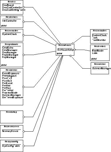
- During start-up, the swHousekeeper object sets up two telemetry objects, formA and formB, sets an internal pointer to one of the objects, and tells that object to allocate a telemetry packet buffer (not shown). Later, once multitasking has started, the main loop of the swHousekeeper task waits for a period of time, and then telemeters the set of statistic counters accumulated during that period.
- A client object, client 1, running under any thread of control, including interrupts, reports a statistic to the swHousekeeper object.
- The swHousekeeper object tells its current telemetry object, in this case formA, to accumulate the statistic into its telemetry packet buffer.
- Periodically, its main loop returns from waiting for the accumulation interval, and proceeds to telemeter the accumulated statistics. It first tells its alternate telemetry object, in this case formB, to allocate and initialize a telemetry packet buffer.
- formB uses the packet allocator object dedicated to software housekeeping, swHouseAllocator, to get a packet buffer. If one is not available at the time of the request, the swHousekeeper object reports it to formA, and waits for the next cycle. In this example, assume that a packet was obtained.
- The swHousekeeper task then sets its internal pointer to point to formB. At this point another client, client 2, then reports a statistic.
- swHousekeeper directs its new current telemetry object, formB, to accumulate the statistic.
- swHousekeeper tells its old telemetry object, formA, to post its telemetry packet for transfer.
- The formA object tells the tlmManager object to post the packet buffer for transfer.
- Later, once the packet has been transferred, the tlmManager releases the packet buffer back to the originating allocator, swHouseAllocator. At this point, the telemetry packet buffer may be re-used by swHousekeeper.
NOTE: This scheme relies on the swHouseAllocator object having at least two software housekeeping telemetry packet buffers to manage. If no packets are available during start-up, the formA will fail to get a packet, and the swHousekeeper system fails. If only one packet is available, the request to formB to acquire a buffer will never be satisfied, and although statistics are being acquired, they will never be sent.
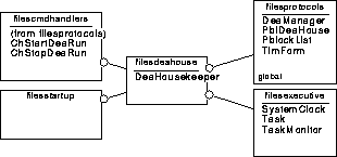
This section provides a simplified picture of how the instrument acquires housekeeping values from the Detector Electronics Assembly (DEA) and sends them to telemetry. For a detailed description of DEA housekeeping services, see Section TBD.
The ACIS software uses the deaHousekeeper task to acquire and telemeter housekeeping values from the Detector Electronics Assembly. Like other tasks in the system, the deaHousekeeper provides binding functions, which are used by other tasks to command the housekeeper to perform certain services.
The following object diagram shows how various DEA housekeeping is configured, and how housekeeping values are acquired and posted to telemetry.
FIGURE 10. DEA Housekeeping Runs Object Diagram
- The cmdManager receives a command packet which contains a DEA housekeeping parameter block to load into the instrument. Using the opcode of the command packet, the cmdManager selects the chLoadDeaHouse object to process the command.
- The chLoadDeaHouse object checks the contents of the parameter block, extracts the slot identifier from the block, and then tells the DEA housekeeping parameter block list object, pblDeaHouse, to replace the existing parameter block corresponding to the slot with the new parameter block.
- Later, the cmdManager object receives a command packet instructing the instrument to start DEA housekeeping. The cmdManager forwards the command to the chStartDeaRun object for execution.
- The chStartDeaRun object checks the command, and tells the deaHousekeeper object's binding function to instruct the task to start acquiring and sending values.
- The deaHousekeeper object's binding function notifies the task portion of the object to start its operations.
- Later, as a result of the notification, the deaHousekeeper task wakes up, and fetches the parameter block to use from the DEA housekeeping parameter block list, pblDeaHouse, and starts its housekeeping operations.
- Once the parameter block has been fetched, the deaHousekeeper object establishes a telemetry object, tfDeaHouse, to manage telemetry buffers and formatting. It tells the telemetry object to get a telemetry packet buffer.
- The tfDeaHouse object goes to the housekeeper's buffer allocator, deaHouseAllocator, to allocate a telemetry buffer. If one is not immediately available, it waits until a buffer is released by the telemetry manager, tlmManager.
- Once the telemetry object has a buffer, the deaHousekeeper tells the deaManager to obtain a housekeeping value from the DEA.
- The deaManager object sends a query command to the DEA using the deaDevice object, and then waits for and reads the reply to the query, returning the replied value back to the housekeeper.
- The deaHousekeeper then adds the housekeeping value to its telemetry buffer. The deaHousekeeper repeats these steps (from step 9) for each housekeeping value specified in the parameter block until all entries have been acquired and stored.
- Once all of the values have been stored, the deaHousekeeper tells the tfDeaHouse to post its buffer to be sent to telemetry.
- The tfDeaHouse object passes its telemetry buffer to the tlmManager object for transmission. The deaHousekeeper object then tells the telemetry object to wait for another buffer, and repeats its housekeeping acquisition cycle (from step 8).
- Later, once the posted telemetry packet buffer has been sent, the tlmManager object releases it back to the DEA Housekeeping packet allocator, deaHouseAllocator. At this point, the buffer is ready to be re-used by the housekeeper.
- Finally, the cmdManager object receives a command to stop DEA Housekeeping, and forwards the packet to the chStopDeaRun object.
- The chStopDeaRun object invokes a binding function of the deaHousekeeper object to stop the run. The deaHousekeeper then completes its current cycle and stops housekeeping.
This section provides a simplified picture of how the instrument performs science data acquisition and processing runs. For a detailed description of science operations, see Section 33.0 , Section TBD, Section 41.0 , Section TBD, and Section TBD.
Science processing is managed using a collection of related objects. The scienceManager object is a task which is responsible for coordinating the operation of a run. It provides binding functions which are used by other tasks to start and stop science runs.
The scienceManager object implements a particular science mode using a particular science mode object. The following example describes a Timed Exposure run, and uses an smTimedExposure object to implement the details of the run.
Any given science mode also has various processing modes. These are handled using a processing mode object. For a given run, one processing mode object is used to process data from one corresponding Front End Processor being used for the run. The example only illustrates one such object, pmEvent.
The following object diagram shows a simplified picture of the overall sequence of events which take place during a science run.
FIGURE 11. Science Run Object Diagram
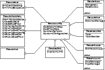
- The cmdManager object receives a packet instructing the system to start a science run. The cmdManager forwards the request to the chStartTimedExp object for execution.
- The chStartTimedExp object interprets the command packet, and tells the scienceManager object's binding function to start a new science run.
- The scienceManager's binding function notifies its task to start a new run.
- Later, as a result of the notification, the scienceManager's task is scheduled to run. It retrieves the parameter block to use (not shown), and tells the science mode object, smTimedExposure to setup for a run.
- The smTimedExposure object uses the deaManager object to issue commands to the DEA to load the CCD Controller Program and Sequencer RAMs (PRAM, SRAM).
- The smTimedExposure object then tells the fepManager object to configure each Front End Processor software.
- Once the setup is complete the scienceManager tells smTimedExposure to dump its parameter blocks (not shown). If a bias computation is needed, the manager tells the mode object to compute the pixel-by-pixel bias maps on each of the configured FEPs.
- The smTimedExposure object tells the fepManager object to start the bias computation routines on each of the configured FEPs.
- For each configured FEP, the fepManager object issues a command to the FEP command mailbox to start the bias computation.
- The FEP I/O Library functions, running on each Front End Processor, read the command.
- The "start bias" command is then interpreted by the Science functions running on each FEP. At this point, the FEP Science functions proceed to wait for data to arrive from their respective CCDs, and compute the pixel bias map values from the acquired images.
- Once all of the FEPs are ready to compute their bias levels, and are waiting for images, the mode object, smTimedExposure, instructs the deaManager object to start the CCD Controller sequencers on the DEA. Once the sequencers start clocking out images, the FEP Science routines proceed to acquire the images, and use the images to build their respective pixel bias maps. Once the bias computation is complete, the FEP Science routines report the completion using their respective Request Mailboxes. The fepManager object detects the completion and reports it back to the smTimedExposure object (not shown). The smTimedExposure object then uses the deaManager to stop the sequencers.
- Once the bias maps have been computed, the scienceManager object instructs the mode object to start acquiring and processing science event data, and if necessary, notifies the biasThief (not shown) to start packing and posting the computed bias maps to telemetry.
- The smTimedExposure object tells the fepManager object to start data processing on all of the configured FEPs. Once they're ready, smTimedExposure re-starts the DEA sequencers.
- As the FEP Science functions acquire images and detect events, they use the FEP I/O Library routines to send the data to the Back End Processor.
- The FEP I/O Library routines append the data and exposure records to the shared-memory ring-buffer.
- As data is placed into the ring buffer, the smTimedExposure object tells the fepManager to read the data.
- The fepManager object then reads the exposure and data records from each FEP's ring-buffer.
- The smTimedExposure object uses a collection of processing objects, pmEvent, to process data. Each pmEvent object is associated with one Front End Processor. As data is consumed from a ring-buffer, the smTimedExposure object tells the corresponding processing object to process the read exposure and data records.
- As the pmEvent object interprets the records and filters events, it uses a science data telemetry object, tfEventData, to pack the un-filtered events into a telemetry buffer. If the telemetry object does not have a buffer, pmEvent instructs it to wait for a telemetry packet buffer. The tfEventData object uses the allocator object dedicated to science processing, scienceAllocator, to wait for and allocate the buffer. Once it has a buffer, the event data is packed into the buffer by tfEventData. Once the tfEventData's buffer is full, the pmEvent object tells the telemetry object to post its buffer for transfer out of the instrument.
- The tfEventData object passes its telemetry packet buffer onto the tlmManager object to be posted for transfer out of the instrument.
- Later, once the telemetry packet buffer contents have been transferred, the tlmManager releases the packet buffer back to the allocator, scienceAllocator. At this point, the telemetry packet buffer can be re-used by science.
- Eventually, the cmdManager receives a command instructing the system to stop performing science. The cmdManager forwards the packet to the chStopTimedExp object for execution.
- The chStopTimedExp object then instructs the scienceManager's binding function to stop the run. The scienceManager's binding function tells smTimedExposure to stop, which then sets an internal flag and notifies the task to stop. When the task detects the stop request, it instructs the FEPs to finish processing. Once the last exposure being processed by the Front End Processors is complete, smTimedExposure stops the DEA CCD Controller sequencers, and posts a summary of the run to telemetry (not shown).
 Table of Contents
 Next Chapter
 Table of Contents
 Previous Chapter
 Table of Contents
 Previous Chapter